Writer: Eric Bearing Limited
Under normal circumstances, INA bearings can only be used in conjunction with shafts and housings. Do you know how to use the INA bearing interference fit assembly? Someone will ask: "Isn't the interference fit assembly means putting the shaft or sleeve parts into the hole? Does the size of the shaft or sleeve and the hole fit slightly larger than the hole?" Can the INA bearing still operate well? ? Below, Eric Bearing Limited will answer your doubts based on the understanding.
1. Why INA bearings adopt interference fit assembly
When the load on the INA bearing rotates relative to the ring, that is, when the direction of the radial load does not change, but the ring rotates; or the ring is stationary but the load rotates around the ring, the mating surface bears The load position will undergo contact deformation, and at the same time, there will be a gap at the opposite position. As a result, the circumferences of the inner part of the mating surface and the outer part will be inconsistent, and the inner part will slip in the inner diameter surface of the outer part. This slippage is slow and is generally called creep. After creep occurs, due to poor lubrication of the mating surface, coupled with the ploughing effect of abrasive particles, the mating surface will be severely worn, resulting in poor rotation of the bearing, heat generation or internal wear of the bearing, and ultimately damage to the bearing. In order to prevent this phenomenon, it is necessary to adopt an interference fit so that there is no gap between the mating surfaces. In addition, when the ferrule needs to be positioned strictly, an interference fit is also required.
2. Advantages of interference fit
(1) The connection is firm, and the degree of tightening can exceed that of key connection and pin connection.
(2) The interference connection reduces the number of parts and simplifies the mechanical structure.
Due to the above advantages, the interference fit is suitable for connections that bear impact loads and are not frequently disassembled.
3. It can be seen that the reliability of interference fit is related to the assembly method. The following example illustrates the assembly method of INA bearing interference fit:
(1) For small interference, it is a light interference fit.
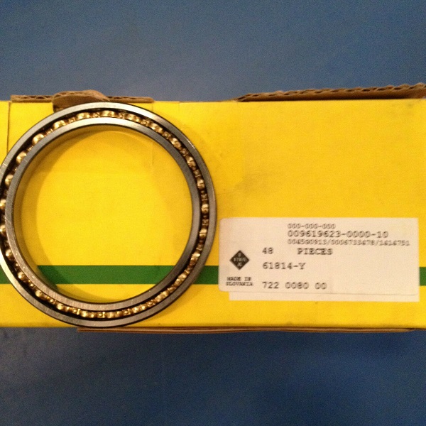
Assemble with steel hammer or press. It is used for precise positioning, overhaul before disassembly or no disassembly. Due to the small interference, most of the above fits cannot transmit load by the generated tightening force. If torque or axial force needs to be transmitted, fasteners must be added. ERIC BEARING LTD can supply many kinds of INA bearing , today share INA 61814 -Y , if interested , click here :
(2) For medium-sized interference, it is a medium-sized interference fit.
Assembled by pressing machine, thermal expansion hole or cold shrinkage shaft method, used for permanent or semi-permanent combination of steel parts, no fasteners are required when transferring medium loads, and fasteners should be added if they are subjected to large or dynamic loads
(3) For larger interference, it is a heavy-duty interference fit. Use thermal expansion hole or cold shrink shaft method to assemble.
It is used to transmit large torque or bear large impact load, and rely entirely on the tightening force generated by interference to ensure a firm connection. Because of the large interference, no fasteners are needed, but the parts are required to have good rigidity and high material strength.
(4) For a large interference fit, it is an extra heavy interference fit. Use thermal expansion hole or cold shrink shaft method to assemble.
Can withstand great torque and dynamic load. There are very few currently used and can be applied only after testing.
4. Select the method of fit according to the limit clearance (or interference)
When the limit clearance or limit interference is known, the fit can be selected by the calculation-look-up table method.
(1) Steps and methods
Calculate the fit tolerance according to the known limit gap (or interference), check the standard tolerance value table according to the fit tolerance to select the tolerance level, and calculate the basic deviation value according to the formula.
According to the basic deviation value, check the basic deviation value table to determine the basic deviation code, draw the tolerance zone diagram and the fit tolerance zone diagram, and analyze whether the selected fit is appropriate.
(2) Calculation of basic deviation of non-reference parts
a. Clearance fit: Because the absolute value of the basic deviation is exactly equal to the minimum gap, you can directly check the basic deviation value table to determine the corresponding basic deviation code according to the known minimum gap.
b. Transition fit: The basic deviation of the shaft is the lower deviation ei (except j), and the hole is the upper deviation ES (except J).
Basic hole system ei = +(Th-Xmax) Basic shaft system ES = -(Ts-Xmax)
(3) Issues that should be paid attention to: In order to ensure the use requirements, the difference between the selected limit clearance (interference) and the original required limit clearance (interference) should be small.
a. For clearance fits, in order to ensure good lubrication and operation of the joints, the selected minimum clearance should be slightly greater than or equal to the original minimum clearance; in order to ensure the service life, the difference between the two maximum clearances is as small as possible.
b. For the interference fit, in order to ensure the connection strength of the joint, the selected minimum interference should be slightly greater than or equal to the original required minimum interference; the maximum interference should be less than or close to the original required maximum interference to avoid materials during assembly damage.
c. For the transition fit, the maximum clearance and interference selected should not be greater than the original required value. Excessive clearance will reduce the coaxial accuracy of the corresponding accessories, and excessive interference will affect assembly and disassembly.
d. In order not to affect the fit performance and production cost, usually, the absolute value of the difference between the selected limit clearance (interference) and the original required limit clearance (interference) should generally not exceed 10% of the original required fit tolerance .
Tel: 00852-30697500
Fax: 00852-30697511
Email: sales@ericbearing.com
Message: Click Here Message!